Inclined Planes
 An
object placed on a tilted surface will often slide
down the surface. The rate at which the object slides down
the surface is dependent upon how tilted the surface
is; the greater the tilt of the surface, the faster
the rate at which the object will slide down it. In physics,
a tilted surface is called an inclined plane. Objects
are known to accelerate down inclined planes because of an
unbalanced force. To understand this type of motion, it is
important to analyze the forces acting upon an object on an
inclined plane. The diagram at the right depicts the two
forces acting upon a crate that is positioned on an
inclined plane (assumed to be friction-free). As shown in
the diagram, there are always at least two forces
acting upon any object that is positioned on an inclined
plane - the force of gravity and the normal force. The
force of gravity (also
known as weight) acts in a downward direction; yet the
normal force acts in a
direction perpendicular to the surface (in fact,
normal means "perpendicular").
An
object placed on a tilted surface will often slide
down the surface. The rate at which the object slides down
the surface is dependent upon how tilted the surface
is; the greater the tilt of the surface, the faster
the rate at which the object will slide down it. In physics,
a tilted surface is called an inclined plane. Objects
are known to accelerate down inclined planes because of an
unbalanced force. To understand this type of motion, it is
important to analyze the forces acting upon an object on an
inclined plane. The diagram at the right depicts the two
forces acting upon a crate that is positioned on an
inclined plane (assumed to be friction-free). As shown in
the diagram, there are always at least two forces
acting upon any object that is positioned on an inclined
plane - the force of gravity and the normal force. The
force of gravity (also
known as weight) acts in a downward direction; yet the
normal force acts in a
direction perpendicular to the surface (in fact,
normal means "perpendicular").The first peculiarity of inclined plane problems is that the normal force is not directed in the direction that we are accustomed to. Up to this point in the course, we have always seen normal forces acting in an upward direction, opposite the direction of the force of gravity. But this is only because the objects were always on horizontal surfaces and never upon inclined planes. The truth about normal forces is not that they are always upwards, but rather that they are always directed perpendicular to the surface that the object is on.

 In
the presence of friction or other forces (applied force,
tensional forces, etc.), the situation is slightly more
complicated. Consider the diagram shown at the right. The
perpendicular component of force still balances the normal
force since objects do not accelerate perpendicular to the
incline. Yet the frictional force must also be considered
when determining the net force. As in all net force
problems, the net force
is the vector sum of all the forces. That is, all the
individual forces are added together as vectors. The
perpendicular component and the normal force add to 0 N. The
parallel component and the friction force add together to
yield 5 N. The net force is 5 N, directed along the incline
towards the floor.
In
the presence of friction or other forces (applied force,
tensional forces, etc.), the situation is slightly more
complicated. Consider the diagram shown at the right. The
perpendicular component of force still balances the normal
force since objects do not accelerate perpendicular to the
incline. Yet the frictional force must also be considered
when determining the net force. As in all net force
problems, the net force
is the vector sum of all the forces. That is, all the
individual forces are added together as vectors. The
perpendicular component and the normal force add to 0 N. The
parallel component and the friction force add together to
yield 5 N. The net force is 5 N, directed along the incline
towards the floor.The above problem (and all inclined plane problems) can be simplified through a useful trick known as "tilting the head." An inclined plane problem is in every way like any other net force problem with the sole exception that the surface has been tilted. Thus, to transform the problem back into the form with which you are more comfortable, merely tilt your head in the same direction that the incline was tilted. Or better yet, merely tilt the page of paper (a sure remedy for TNS - "tilted neck syndrome" or "taco neck syndrome") so that the surface no longer appears level. This is illustrated below.
 As
an example consider the situation depicted in the diagram at
the right. The free-body diagram shows the forces acting
upon a 100-kg crate that is sliding down an inclined plane.
The plane is inclined at an angle of 30 degrees. The
coefficient of friction between the crate and the incline is
0.3. Determine the net force and acceleration of the
crate.
As
an example consider the situation depicted in the diagram at
the right. The free-body diagram shows the forces acting
upon a 100-kg crate that is sliding down an inclined plane.
The plane is inclined at an angle of 30 degrees. The
coefficient of friction between the crate and the incline is
0.3. Determine the net force and acceleration of the
crate.Begin the above problem by finding the force of gravity acting upon the crate and the components of this force parallel and perpendicular to the incline. The force of gravity is 980 N and the components of this force are Fparallel = 490 N (980 N • sin 30 degrees) and Fperpendicular = 849 N (980 N • cos30 degrees). Now the normal force can be determined to be 849 N (it must balance the perpendicular component of the weight vector). The force of friction can be determined from the value of the normal force and the coefficient of friction; Ffrict is 255 N (Ffrict = "mu"*Fnorm= 0.3 • 849 N). The net force is the vector sum of all the forces. The forces directed perpendicular to the incline balance; the forces directed parallel to the incline do not balance. The net force is 235 N (490 N - 255 N). The acceleration is 2.35 m/s/s (Fnet/m = 235 N/100 kg).
Practice
The two diagrams below depict the free-body diagram for a
1000-kg roller coaster on the first drop of two different
roller coaster rides. Use the above principles of vector
resolution to determine the net force and acceleration of
the roller coaster cars. Assume a negligible affect of
friction and air resistance. When done, click the button to
view the answers.
The affects of the incline angle on the acceleration of a roller coaster (or any object on an incline) can be observed in the two practice problems above. As the angle is increased, the acceleration of the object is increased. The explanation of this relates to the components that we have been drawing. As the angle increases, the component of force parallel to the incline increases and the component of force perpendicular to the incline decreases. It is the parallel component of the weight vector that causes the acceleration. Thus, accelerations are greater at greater angles of incline. The diagram below depicts this relationship for three different angles of increasing magnitude.
 Roller
coasters produce two thrills associated with the initial
drop down a steep incline. The thrill of acceleration is
produced by using large angles of incline on the first drop;
such large angles increase the value of the parallel
component of the weight vector (the component that causes
acceleration). The thrill of weightlessness is
produced by reducing the magnitude of the normal force to
values less than their usual values. It is important to
recognize that the thrill of weightlessness is a feeling
associated with a lower than usual normal force. Typically,
a person weighing 700 N will experience a 700 N normal force
when sitting in a chair. However, if the chair is
accelerating down a 60-degrees incline, then the person will
experience a 350 Newton normal force. This value is less
than normal and contributes to the feeling of weighing less
than one's normal weight - i.e.,
weightlessness.
Roller
coasters produce two thrills associated with the initial
drop down a steep incline. The thrill of acceleration is
produced by using large angles of incline on the first drop;
such large angles increase the value of the parallel
component of the weight vector (the component that causes
acceleration). The thrill of weightlessness is
produced by reducing the magnitude of the normal force to
values less than their usual values. It is important to
recognize that the thrill of weightlessness is a feeling
associated with a lower than usual normal force. Typically,
a person weighing 700 N will experience a 700 N normal force
when sitting in a chair. However, if the chair is
accelerating down a 60-degrees incline, then the person will
experience a 350 Newton normal force. This value is less
than normal and contributes to the feeling of weighing less
than one's normal weight - i.e.,
weightlessness.Angles of Friction
Equations
Nomenclature
| symbol | description |
| φs | angle of static friction |
| φk | angle of kinetic friction |
| μs | coefficient of static friction |
| μk | coefficient of kinetic friction |
| N | normal component of the reaction surface |
Explanation
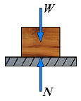
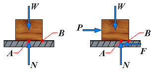
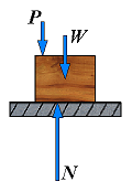
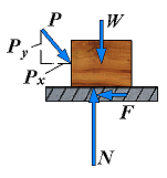
It is sometimes convenient to replace the normal force N and the friction force F by a resultant R. Consider a block of weight W resting on a horizontal plane surface:
| No friction | R = N | 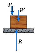 | If no horizontal force is applied to the block, the resultant R reduces to the normal force N. |
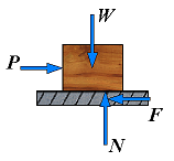
| No motion | F = Px φ < φs | 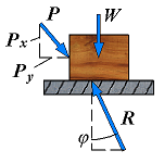 | However, if the applied force P has a horizontal component Px which tends to move the block, the force R will have a horizonatal component F and, thus, will form an angle φ with the normal to the surface as shown. |
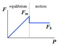
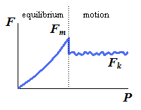
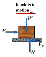
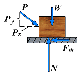
| Motion impending | Fm = Px φ = φs | 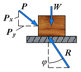 | If Px is increased until motion becomes impending, the angle between R and the vertical grows and reaches a maximum value. |
This maximum value is called the angle of static friction and is denoted by φs. From the geometry of the previous figure, the equation is:
| tan φs = |
| = |
|
| tan φs = μs |
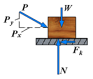
| Motion | F = Px φ < φs | 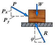 | If motion actually takes place, the magnitudes of the friction force drops to Fk; similarly, the angle φ between R and N drops to a lower value φk, called the angle of kinetic friction. |
From the geometry of the previous figure, the equation is:
| tan φk = |
| = |
|
| tan φk = μk |
Another example may show how the angle of friction can be used to advantage in the analysis of certain types of problems. Consider a block resting on a base and subjected to no other force than its weight W and the reaction R of the board. The board can be given any desired inclination.
| No friction | R = N | 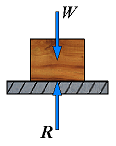 | If the base is horizontal, the force R exerted by the board on the block is perpendicular to the base and balances the weight W. |
| No motion | F = Px φ < φs | 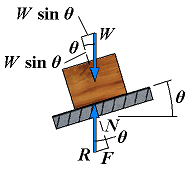 | If the base is given a small angle of inclination, θ, the force R will deviate from the perpendicular to the base by the angle θ and will keep balancing W; it will then have a normal componenet N of magnitude N = W cos θ and a tangential component F of magnitude F = W sin θ. |
| Motion impending | Fm = Px φ = φs | 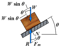 | If the angle of inclination continues to increase, motion will soon become impending. At that time, the angle between R and the normal will have reached its maximum value φs. The value of the angle of inclination corresponding to impending motion is called the angle of repose. Clearly, the angle of repose is equal to the angle of static friction φ. |
| Motion impending | Fm = Px φ = φs | 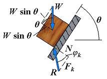 | If the angle of inclination θ is further increased, motion starts and the angle between R and the normal drops to the lower value φk. The reaction R is not vertical any more, and the forces acting on the block are unbalanced. |